


Posted 3 years ago
 RichmondLori
(358 items)
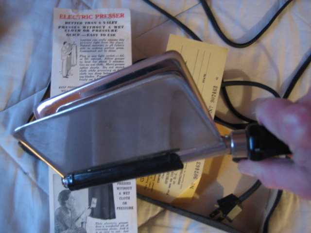
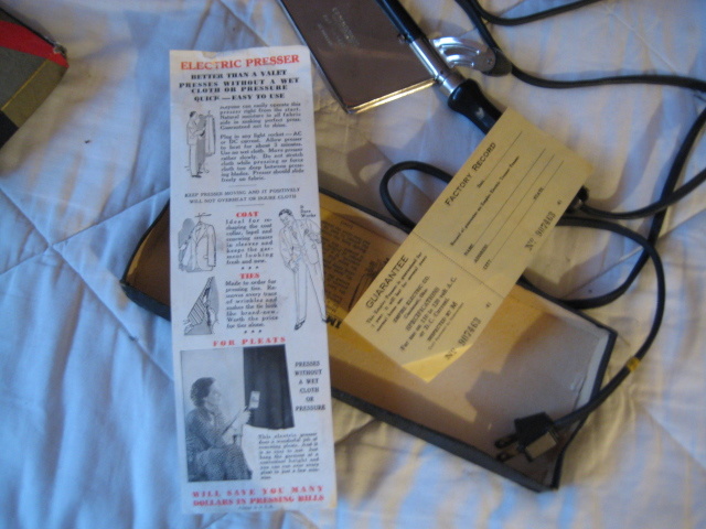
EMPIRE Electric Presser in Box for Trousers, Coat Sleeves, Lapels, Ties.
made by Empire Electric Co. in Cincinnati
Description
y 15, R. R. BOLLMAN CREASING APPARATUS Filed NOV. 24 1935
INVENTOR ATTORNEYS Patented May 15, 1934 UNITED s'lwrlas 1,95%}.047 CREASING APPARATUS Roland R. Bellman, Cincinnati, Ohio, assignor to The Munny Manufacturing Company, Cincinnati, Ohio, a corporation of Ohio Application November 24, 1933, Serial No. 699,581
- 3 Claims. (Cl. 219-21) This invention relates to improvements in devices for creasing garments and other textile articles and is particularly directed to improvements in small portable electrically heated hand tools of the nature disclosed in the patent to Bellman No. 1,889,432, issued November 29, 1932.
It is the object of this invention to provide a creasing device of the above mentioned type which is of extremely simple construction and therefore economical and easy to manufacture, and which is highly efllcient and cannot be improperly handled in its application to the garment. The creasing blades are of highly simplified plate structure and are related to each other and to the heating unit by means of a mounting which does not permit of injury'to the garment such as could occur in the event of direct contact with the heating unit. r
Other objects and certain advantages will be more fully apparent from a description of theaccompanying drawing, in which:
Figure 1 is a side view of the improved creasing device.
Figure 2 is a sectional view of the device take on line ii-+2, Figure 1. 7
Figure 3 is a general view illustrating the device in use.
Referring to the drawing, the tool or device comprises creasing blades 5, 5, a handle 6 and a heating unit '1. The heating unit '7 is fixed to and extends from the handle 6 and carries the blades 5, 5.
The handle is of insulating material such as wood and is tubular. A metal tube 8 carrying the heating coil 9 is extended into the outer end of the handle and fixed therein. Electrical contactors 10, 10, are extended through an insulating bushing 11 of the handle and an insulating bushing 12 of the metal tube and are connected to the end of the coil 9, the end of which is adiacent the end of the handle within the tube 8. A ferrule 13 caps the end of the handle surrounding the extended heating coil tube. An abutment button 14 is secured in. the outer end of the tube supporting the outer end of the coil.
The creasing blades are members of a single plate element 15. The plate in the formation of the creasing blades is overlapped intermediately and is formed along the bent portion to provide a cylindrical sleeve portion 16 engaged over the heating tube. A plurality of rivets 17 secure the blades together at their inner edges to complete the tubular cylindrical portion which mounts the blades. This element is slipped over the heating tube or unit and is held in place by means of the removable button 14 at the outer end thereof.
From the line of the rivets, the blades flare outwardly gradually and their outer edgesare curved or bent as at 18 to readily permit introduction of the textile material between the blades and to permit easy sliding movement of the blades along the material being creased.
- It is highly important that the textile material be kept from contact with the .heating unit and at the same time that a good creasing engagement be procured. For this reason the rivets are highly eifective in limiting insertion of the garment between the blades. At the same time the gradual decrease in the spacing of the blades to a contact along the line of the rivets because of the'acute relation of the blades provide a good creasing slot and a very sharp channel. It is impossible for the operator to place the garment in too close proximity to the heating unit and the device is rendered safer and more fool-proof than heretofore.
Having described my invention, I claim:
' 1. A creasing device, comprising, a cylindrical heating unit having a handle at one end thereof, creasing blades formed from a single sheet of plate material engaged on the heating unit, said blade forming plate material including a cylindrical sleeve portion disposed around the heating element, and a series of fastening deqces drawing the blades together into contact along the edge of thecylindrical portion for limiting insertion of the garment between the blades, and said blades gradually flared outwardly for the creasing insertion of a garment.
2. A creasing device, comprising, an elongated heating unit having a handle at oneend thereof, creasing blades formed from a single sheet. of plate, said plate engaged on the heating unit, 7
said sheet of plate including a sleeve portion disposed around the heating element, said blades disposed in contact along the edge of the cylin drical portion for limiting insertion of the garment between the blades, and said blades gradually flared outwardly for a creasing insertion of the garment.
3. A creasing device, comprising, a cylindrical heating unit having a handle at one end thereof providing an abutment and an abutment element at the. other end thereof, creasing blades formed from a single sheet of plate material engaged on the heating unit, said blade forming plate material including a cylindrical portion disposed around the heating element between the abutment of the handle and the abutment element, and a series of fastening devices drawing the blades together into contact along the edge of the cylindrical portion for limiting insertion of the garment between the blades, and said blades gradually flared outwardly for the creasing insertion of a garment.
, ROLAND R. BOILMAN.
Cited By (1)
Publication number Priority date Publication date Assignee Title
US2515781A * 1949-04-23 1950-07-18 Gen Electric Electric heating unit
One VERY innovative device!! Having the original box and instructions is fantastic. Very informative writeup!!
Scott, thank you. I really did try it (didn't try with the pants on) and it works, great crease. To bad I didn't have this when I worked for a living and wore a uniform, it sure would have been so nice to have. Lori
And thank you for all the loves:
Hoot60
Newfld
vetraio50
Watchsearcher
fortapache
dav2no1
kwqd
clockerman
jscott0363